


Introduction
This week, I read the first 80 pages of Practical Python Programming for IoT while programming along. The following is a journal summarizing what I learned, without going into much detail.
Setting Up and Getting Started
Practical Python Programming for IoT comes with a long shopping list of sensors, cables, resistors, a single-board computer, and more. I bought most of it - around 250€ in total.
A Raspberry Pi 4 model B with OS Buster is used for the exercises.
Run a Script on Boot
One of the first tutorials was about running a script on boot. At the core of it is the following commands:
$ crontab -e(select an editor)
Add the following line to the document:
@reboot /path/to/<filename>.sh &
In the bash script, <filename>.sh, we added code that runs a Python script and then saves the time it was run in a log file. The interesting part is that I can now automatically run a set of instructions when starting the Raspberry Pi.
I haven't read up on crontab, but @reboot must be the command that runs the script on reboot. I assume that other commands can, for example, run the script at a specific time each day, or be triggered by an event.
PiGPIO Daemon
I set up the PiGPIO daemon service so it runs on start. This is necessary for using the Python PiGPIO library. I used the following commands:
$ sudo systemctl enable pigpiod$ sudo systemctl start pigpiod
Resistors
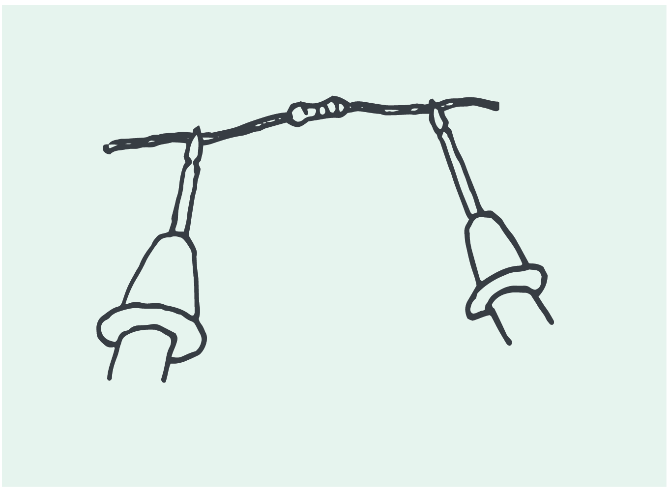
My resistors had different color bands than the ones online. I found out with a multimeter that I had the one I needed: 200 Ω. The multimeter was simple to use - just set it to Ω, then touch the tips of the multimeter on each leg of the resistor (sorry, I don't yet know the correct terminology) like so:
Libraries
Two libraries were used in the exercises to control the same thing, an LED:
gpiozero: A high-level library for more user-friendly use. It abstracts away more implementation details than PiGPIO.
PiGPIO: More low-level than gpiozero with direct control of pins
Projects
Following along with the book, I implemented several projects. It started with attaching an LED, button and resistor to a breadboard, and connecting them to pins on the Raspberry Pi. A part of implementing the projects is to learn to read electronic diagrams. The diagram for the chapter 2 projects looked like this:
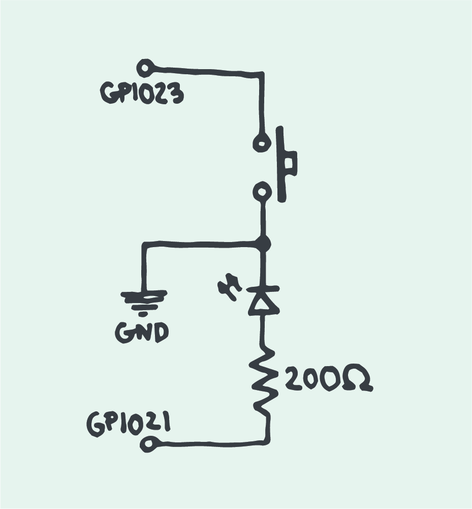
GPIO 21, GPIO 21 and GND are pins on the Raspberry Pi. The arrow with the line is the LED, the zigzag-line is the resistor, and the little hat in the upper right part is the button.
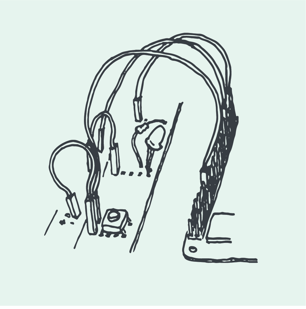
Assembled, it looked like this (breadboard on the left, Raspberry Pi on the right):
For the button, it was necessary to add a bounce time of 0.1 seconds. Bounce is electrical noise that can occur when pressing a button. E.g., before it’s completely pressed, it might go quickly back and forth between on and off (state changes), because of the noise. The bounce time tells our raspberry to ignore these shifts for 0.1 seconds. The button will be unresponsive until the time has passed.
We added signal.pause() to the end of our scripts to prevent them from exiting. If not, it would run through the code and exit immediately.
Projects were implemented in two different versions: One with PiGPIO and one with gpiozero to see how they differ from each other.
I implemented the following LED projects:
Make an LED turn on and off X number of times.
Make an LED turn on and off when pressing the button.
Make an LED turn on and off, and blink, via dweet.io.
LED Control Through dweet
This was an incredibly cool project - by using dweet.io, we made a script that can turn the LED on and off over the internet. It can also make it blink.
With these links, I can control the LED on my raspberry:
ON: https://dweet.io/dweet/for/<my_uid>?state=on
OFF: https://dweet.io/dweet/for/<my_uid>?state=off
BLINK: https://dweet.io/dweet/for/<my_uid>?state=blink
The script receives the state, e.g. "on", and runs the associated code.
We get our unique identifier, <my_uid> with uuid.uuid1(). This is used in the dweet url for communicating with our device. I was wondering how this ID can really be unique, and avoid conflicts with other dweet users, but in the documentation, it says that
...uuid1() may compromise privacy since it creates a UUID containing the computer’s network address.
Summary
That was all for week 1. I learned to run a script on boot, got started with electronic diagrams, connecting electronics to the Raspberry Pi and implemented different ways of controlling an LED though Python scripts.